Siting of Septic Systems in
Using a Desktop GIS
GIS in Water Resources/GIS for Civil
Engineers
Fall, 2001
Team Members:
Tyler Smith
Ricardo Soto
Aaron Swank
1.0. Introduction
The protection of water quality is an important issue for
communities around the state of
2.0. Design Pathway
The
following flowchart provides a summary of our approach to developing a GIS for suitability
of septic systems in
Figure 2.1. GIS Design Pathway.
3.0. Design Criteria
Septic systems are designed and installed in
Table 3.1. Septic
System Design Requirements.
|
Design Criteria |
Value |
|
Depth to groundwater |
At least
24 inches below the bottom of the absorption system excavation and at least
48 inches below finished grade |
|
Percolation rate, defined by soil texture |
TYPE RATE(min/in) SYMBOL (USDA Soil Classification)1 Good 1-15 Sand, Loamy Sand2 Fair 16-30 Sandy Loam, Loam3 Poor 30-45 Loam, Silty Loam4 Marginal 46-60 Sandy Clay Loam. Silty Clay Loam,(g).
5 Unacceptable Clay Loam, Clay Bedrock, fractured bedrock, hardpan, (including
unacceptable ground water table elevations) |
|
Distance from public water supply source to septic tank. |
100 feet |
|
Distance
from non-culinary well or spring to septic tank. |
25 feet |
|
Distance
from individual or nonpublic water supply source (spring) to septic tank |
50 feet |
|
Distance
from culinary water supply line to septic tank |
10 feet |
Source:
Septic
systems in
Table 3.2.
Definition of
|
Drinking Water Protection Zone |
Protection Criteria |
|
1 |
100-foot radius from the well or margin of the collection
area. |
|
2 |
250-day groundwater time of travel to the margin of the
collection area, boundary of the aquifer(s) which supplies water to the
groundwater source, or groundwater divide, whichever is closer. |
|
3 |
3-year groundwater time of travel to the margin of the
collection area, boundary of the aquifer(s) which supplies water to the
groundwater source, or groundwater divide, whichever is closer. |
|
4 |
15-year groundwater time of travel to the margin of the
collection area, boundary of the aquifer(s) which supplies water to the
groundwater source, or groundwater divide, whichever is closer. |
It also states
“No person shall place, maintain, or operate onsite sewage disposal
from a septic tank within the Zone 1, Zone 2,
or within 300 feet of
any public street in which a public sewer is
laid. Septic systems in
Zones 3 and 4 shall comply with the Utah Department of
Health
Care of Waste Disposal Regulations, Part IV
and Part V.”
These criteria were used in determining areas of septic tank
suitability for this GIS.
4.0. Data Collection
The
entire team (Aaron, Ricardo, and Tyler) was involved in the data acquisition
process.
5.0. Data Analysis
Once the data layers were obtained, GIS analysis
could begin. The first step was to identify whether or not the same projection
was used for each theme. It was found that data from the AGRC was projected
using UTM (NAD 83) Zone 12 in decimal degrees, and the data obtained from the
Cache County Regional Planning Office was in meters. Each theme was projected
in meters in order to preserve the correct scale.
The second step was to evaluate the information
presented in each theme in regard to the criteria for septic tank suitability
outlined in the state of Utah Administrative Rule R317-004 and the Cache County
Zoning Ordinance. Data that fit the criteria were locations of drinking water
sources, groundwater recharge areas, and drinking water protection zones. These
data were used in further analysis.
The third step in analysis was to determine the
location of drinking water protection zones in
The fourth step involved creating a new shapefile
from the recharge zone theme. The recharge zone theme was classified into
discharge, primary recharge, and secondary recharge areas. Primary and secondary recharge zones are
unsuitable for on-site wastewater treatment system installation. These two
layers were combined into a new shapefile to
further delineate unsuitable areas.
This new shapefile was combined with zones 1 and 2
from the drinking water protection zones theme
generated in step three. The geoprocessing extension was added to ArcView in
order to use the geoprocessing wizard. The union tool was then used to create a
new theme combining primary and secondary groundwater recharge zones and
drinking water protection zones 1 and 2, This new
theme was called Unsuitable Areas.
Parcel information was then added in order to
determine which parcels were suitable for on-site wastewater systems. When the
“select by theme” tool was used to find all parcels “completely within” the
unsuitable area, it was found that not all the parcels that seemed to meet this
criteria were selected. It was discovered that the layer created by the “union”
tool kept drinking water protection and groundwater recharge zone delineations that affected the analysis. This
problem was overcome by making the layer created by the geoprocessing “union”
tool into a single theme without any zone delineations. This theme was then
added to a new view containing parcel ownership
information for
This view provided a visual representation of the
suitable and unsuitable areas for on-site treatment system installation, but another
aspect of the project was the creation of a query mode product. Query criteria
of “Yes”, “No”, and “Conditional” were determined based on whether a parcel
lies completely outside, completely inside, or partially inside an unsuitable
area respectively. The “select by theme” tool was used to first determine the
parcels that were “completely within” the unsuitable boundaries. The feature
table was then opened for editing and a field titled “Septic” was added. Using
the “field calculator” tool, the selected parcels were assigned a value of “No”
in the “Septic” field. The “select opposites” tool was then used to determine
the parcels that were in effect “completely outside” the unsuitable areas.
Using the “field calculator” tool once again, the selected parcels were
assigned a value of “Yes” and added to the table. In order to determine the
parcels that were partially in an unsuitable area, the parcels with a value of
“Yes” and “No” were selected and the “select opposites” tool chosen again. All
selected parcels were assigned a value of “Conditional” and added to the field.
The result of the table editing was creation of a new field that may be queried
with respect to septic tank suitability. This represents the query mode aspect
of the project, and may be accessed from the view titled “Query View”.
The final step was to create a view using the new
“Yes”, “No”, and “Conditional” parameters to classify all parcels in
6.0 Final Products
The
goal of the project was to create a desktop GIS program with both product and
query mode potential that may be used by a county planner as a decision making
tool. The query mode portion of the GIS allows a person to determine whether a
specific parcel is suitable for installation of a septic system. A parcel may
be queried using tax identification number, parcel identification, parcel number,
owner name, or owner address. The GIS will select the particular parcel, but in
order to see it in the view, the “zoom to selected” button should be used. This
tool will bring the selected parcel into full view. The details of the parcel
may be viewed using the “identify” tool. Septic tank suitability may be
identified by viewing the “Septic” field at the bottom of the table. The query
will return a value of either “yes”, “no”, or “conditional” in this field,
corresponding to septic tank suitability in that particular parcel. An example
of a query and parcel identification is shown in Figure 5.1.
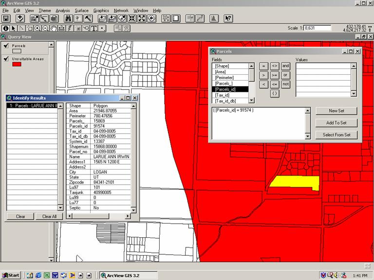
Figure 5.1. Query 1: Unsuitable Site.
The query returned “No” for
septic tank suitability as the entire parcel lies with an unsuitable zone.
An
example of a query using parcel number is shown in Figure 5.2.
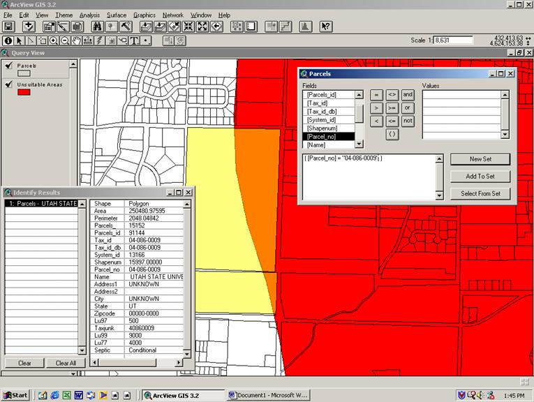
Figure 5.2. Query 2: Conditional Suitability.
This query returned “Conditional”
for septic tank suitability as part of the parcel lies within an acceptable
zone and part of the parcel lies within an unsuitable zone. Further
investigation of the exact location of the proposed system would be required
before a decision is made.
Figure 5.3 shows a query using the
address of the owner of a particular parcel.
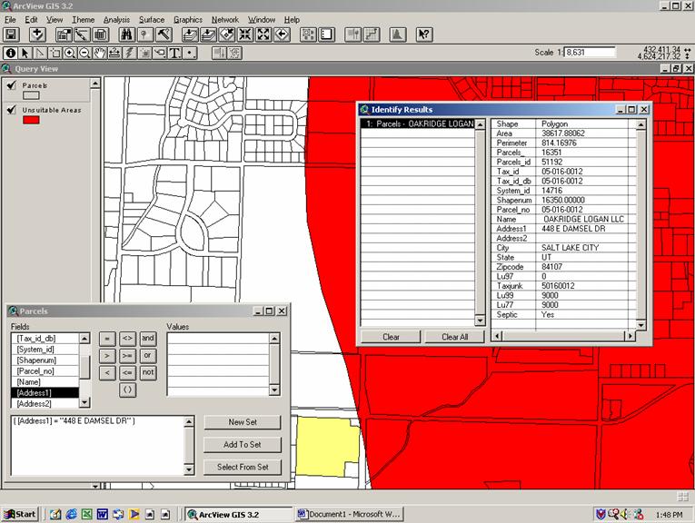
Figure 5.3. Query 3: Suitable Area for Septic Tank.
The query returned “Yes”,
indicating the parcel lies completely within an acceptable zone for installation
of an on-site wastewater treatment system. The system may then be designed
following site specific analysis.
Other
examples of other queries possible with this GIS include, but are not limited
to: (1) What portions of
The product mode aspect
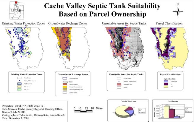
of the project is represented in the final layout.
This map shows the criteria used in establishing the suitable, unsuitable, and
conditional zones for installation of septic systems. These areas are defined
by the drinking water protection zones (Zone 1 and
2) and groundwater recharge areas (Primary
and Secondary Areas).
A final project document
was compiled onto a CD using the Archive_Project_PC13.avx extension obtained
from the ESRI website. This extension reads the only the project file and copies
all the data and extensions from this file to a target directory. In this
manner, only the files associated with this particular project are included on
the CD for ease of data use and management.
7.0. Conclusions and Recommendations
The
parcels in
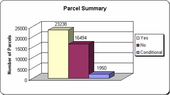
Figure 6.1. Septic Tank Suitability Summary by Total Number of
Parcels.
Using the parcel totals in the figure,
approximately 56% of all the parcels in
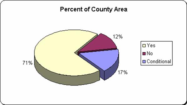
Figure 6.2. Septic Tank Suitability by Percent of Total
As
seen in the figure, 71% of the total area in
The value
of suitable areas in both figures is assumed high for several reasons. First,
the septic tank design criterion of slope was not included in the analysis.
Since only drinking water protection zones and groundwater discharge areas were
used, the mountain areas east of
Second,
although septic tank suitability is highly dependent on soil type and texture, the
soils theme was not included in this analysis. A theme including data from the Cache
County Soil Survey was obtained from several sources. This data included soil
type as well as its associated engineering significance. However, the metadata
could not be obtained after significant effort, and the soil theme was excluded
from the septic tank suitability analysis. This theme may be used in the
current project to simply identify soil type at a particular location. It was
also discovered that the soil survey information was not consistent between
sources. Different soil types were identified for the same parcel of land using
data from different sources. The accuracy of the data was evaluated using the
Cache County Survey book obtained from the United States Department of
Agriculture. Addition of this data into the analysis functions is recommended
for future assessment. However, careful examination of this data is necessary
before making it available to the public.
Another
theme that would have been useful for analysis is the depth to groundwater data
for
Although
this GIS is specifically related only to
References
Important Historical
Farmlands of
Lemon,
Teuscher, Mark. Cache
United
States Department of Agriculture Soil Conservation Service and
“Rule 317-4. Onsite Wastewater
Systems.” Utah Department of Environmental Quality.
November, 2001. http://www.rules.state.ut.us/publicat/code/r317/r317-004.htm